Heat Pumps for Energy Efficiency in US Residential Sector
Info: 9637 words (39 pages) Dissertation
Published: 9th Dec 2019
Tagged: ConstructionEnergy
Table of Contents
Abstract
One of the greatest challenges facing society today is the management of global energy resources in light of climate change. In a rapidly changing global environment, it is imperative to assess our energy use and move towards more sustainable solutions. The residential sector plays a big part in the global energy demand. A recent look at energy usage in the U.S Residential Sector confirmed a long-running trend: space heating and space cooling are among the largest consumers of energy. The adoption of various technological improvements contributing to an increase in efficiency for residential space heating and cooling must be considered. Among such technologies are heat pump systems, which use less electricity than traditional electric heating, do not create carbon emissions and are safer than furnaces that burn fuel. However, heat pumps can be further optimized for performance and made to be more efficient. The paper explores heat pumps and their applications in the modern world, and discusses ways to improve efficiency of heat pumps by optimizing their performance.
Objective
The objective of increasing energy efficiency and reducing operating costs of heat pump systems needs to be achieved while simultaneously ensuring robustness, simplicity of operation and ease of maintenance. The paper will investigate strategies to optimize system performance. This will be done by looking at components of heat pump systems in detail and understanding their mechanism and role within the system. Various designs of the different components that constitute heat pump systems will be considered and compared. The conclusion of the study will provide valuable information in support of heat pump systems as a viable alternative to the more popular furnace and electric heating solutions to space cooling and heating.
Scope
The paper focuses on the use of heat pumps in the U.S. residential sector. The climate and geography of the United States are quite diverse, with the Western Coast experiencing a warm climate and the North-Eastern region experiencing cold climate. This allows for heat pumps to be tested and run in a variety of conditions, which provides more data for optimizing performance under varying conditions. Focusing on the U.S. residential sector specifically will also help reduce scope creep by keeping the project boundaries well-defined.
Introduction
Background
A heat pump is an electrical device that draws heat from one location and transfers it to another. The heat pump has its origins in the twentieth century, and has seen widespread usage since its original inception into the market.
Heat pumps work on a refrigeration cycle. Heat pumps transfer heat by circulating refrigerant through a cycle of evaporation and condensation. Refrigerant is a special fluid found in either fluid or gaseous state that readily absorbs heat from the environment. A compressor pumps the refrigerant between two heat exchanger coils. Refrigerant is evaporated at low pressure in one of the coils. While in its gaseous state, it absorbs heat from its surroundings. The refrigerant is subsequently compressed on its way to the second coil, where it condenses at high pressure. At this point, it releases the heat it absorbed earlier in the cycle.
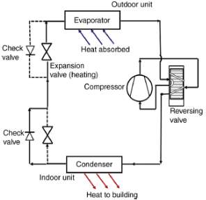
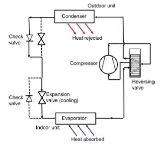 Figure 1-A below shows a simple reversible air/air system in cooling mode. The working fluid is
Figure 1-A
Figure 1-B
boiled in its liquid state in an evaporator at a pressure and temperature, TL, low enough to provide cooling. A work-driven compressor then increases pressure and hence, temperature, of the refrigerant vapor. The hot, high-pressure gas is directed to the outdoor unit acting as the condenser, which cools and condenses the liquid, allowing it to reject heat at a temperature that of the surroundings, TM. Having rejected its heat of condensation, the fluid changes back into liquid state. The condensed liquid then flows through the check valve before passing through an expansion valve that expands the liquid and lowers fluid pressure. The fluid is finally directed back into the evaporator, where it can again provide cooling at a low temperature. Figure 1-B shows the reverse process. Since the flow of working fluid has reversed, the heat exchanger, which was the evaporator, now acts as the condenser, and vice versa. The reversing valve is used to enable the system to act in either mode. When the piston in the reversing valve moves up, the ports are changed so that the system flow is reversed and the unit heats the building.
The heat pump cycle is fully reversible, which is why heat pumps are used to provide year-round climate control for residential and commercial properties. The reversible properties allow heat pumps to be used for both heating and cooling. Heat naturally flows from high temperature to low temperature. Heat pumps, however, can force heat flow in the reverse direction using a small amount of drive energy. Because of this, they are depicted as a heat engine in reverse operation. While heat engines generate work, heat pumps require work to operate.
All refrigeration and heat pump devices using air as a medium should be protected by filters to prevent dust and pollutants from entering the devices and rendering them ineffective. Devices using liquids can have double-pipe, shell-and-tube or plate heat exchanger types. Waste fluids may be contaminated by the process; heat exchangers for waste fluids must be cleanable, and cleaned and maintained frequently. Furthermore, all heat exchange equipment should be fitted with temperature sensors at the inlet and outlet of both fluids, so that operation can be monitored.
Theory
Ideal Reversible Carnot Cycle
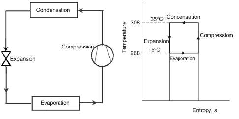
Figure 2-B
Figure 2-A
Figure 2-A shows the circuit diagram and Figure 2-B shows the temperature-entropy diagrams of an ideal reversed Carnot cycle. In this cycle, fluid of certain unit mass undergoes four processes after which it resumes its original state. The compression and expansion processes, shown as vertical lines, are isentropic processes and are reversible in nature. The addition and rejection of heat during condensation and evaporation occurs at constant temperature, which is why these processes are depicted as horizontal lines. Work is transferred into the system during compression and transferred out of the system during expansion.
Vapour Compression Cycle
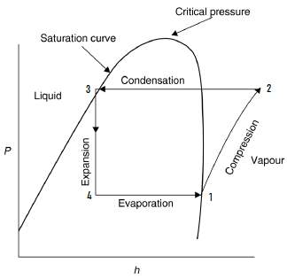
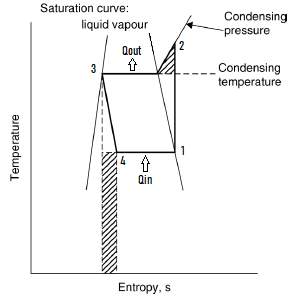
Figure 3-A
Figure 3-B
The vapour compression cycle is used for refrigeration instead of gas cycles. This is because the vapour compression cycle enables a far greater quantity of heat to be extracted than a gas cycle for a given refrigerant mass flow rate. A liquid boils and condenses at a temperature that is dependent on its pressure. In boiling, it gains the latent heat of evaporation and in condensing, the latent heat is released.
Figure 3-A shows the pressure-enthalpy diagram of a vapour compression cycle and Figure 3-B shows the temperature-entropy diagram for an ideal vapour compression cycle.
The breakdown for the cycle is as follows:
- 1-2 (compressor) Isentropic compression (i.e. s1 = s2)
- 2-3 (condenser) P = constant (i.e. P2 = P3) and heat rejection
- 3-4 (expansion valve) Throttling, isenthalpic
- 4-1 (evaporator) P & T = constant (i.e. P4 = P1 and T4 = T1) and heat addition
Some additional points to note are:
- Compressor: WIN = h2 – h1 use: h2 at corresponding pressure and temperature in superheated region and h1 = hg@P1
- Condenser: QOUT = h2 – h3 use: h3 = hf@P3 (QOUT < 0 due to heat being released)
- Expansion Valve: h3 = h4 (isenthalpic) use: h4 to find x4
- Evaporator: QIN = h1 – h4
Heat is added to the fluid at lower temperature and pressure, which provides sufficient latent heat for the fluid to vaporize. At State 1, the fluid is a saturated vapour. This vapour is then mechanically compressed to a higher pressure and a corresponding saturation temperature at which its latent heat can be released so that the fluid can turn back into a liquid. The energy used to compress the vapour is converted into heat, which increases the vapour’s temperature and enthalpy, so that at the end of the compression process, the vapor state is in the superheated part of the diagram (i.e. outside the saturation curve on its right). The process in which heat of compression increases enthalpy of gas is known as adiabatic compression. Figure 3-B shows the drop in temperature from State 2 to 3. This is because the final compression temperature is typically greater than condensation temperature. Fluid temperature drops and the fluid turns into saturated vapor before condensing under isobaric conditions. Figure 3-B also shows a shaded area under State 2 of the process, which represents deviation from the reversed Carnot cycle. Unlike the reversed Carnot cycle, the vapour compression cycle continues past condensing temperature. The shaded area represents the extra work added to the process when it carries on until condensing pressure is achieved. Fluid at State 3 is a saturated liquid. Expansion is a constant enthalpy process and is represented by a vertical line in Figure. Heat is not absorbed nor rejected during this process since the liquid fluid is merely passing through a valve. Some of the fluid flashes into vapour form to remove energy to allow cooling. This lost work is the second deviation of the process and is depicted as a shaded rectangle in Figure 3-B.
All four components associated with the compression cycle are steady-flow devices. Therefore, all four processes can be analyzed as steady-flow processes. The refrigerant flow rate and property values are assumed to be steady as well. Assuming that kinetic and potential energy changes are negligible, the following equation can be derived:
Q + m(h1) = w + m(he) (Bernoulli’s Equation)
Steady Flow Energy Equation (SFEE) for the evaporator stage is: Q + mh4 = mh1. SFEE for the compressor stage is: W + mh1 = mh2. There is no Q term due to adiabatic compression of fluid, for which there is no heat transfer. SFEE for the condenser cycle is: mh2 = Q + mh3. Lastly, SFEE for the expansion valve is: h3 = h4, since the work and Q are assumed to be 0 and the masses cancel out. This equation makes sense since the process is isoenthalpic.
Refrigerant
A refrigerant is a special fluid used for heat transfer in heating pumps and refrigeration systems. Most refrigerants absorb heat during the evaporation stage at low temperature and pressure and reject heat during the condensation stage at a higher temperature and pressure. Some refrigerants are known to produce a refrigeration effect when they throttle and expand in the refrigeration cycle. The change in enthalpy in the evaporator is known as the refrigeration effect. This effect refers to the amount of heat that each unit mass of liquid refrigerant absorbs when it evaporates. By comparison, a system without sub-cooling produces less refrigeration effect.
Various refrigerants are available for usage in mechanical heat pumps. Each refrigerant has certain advantages and disadvantages that varies on several criteria.
Pressure
The condensation pressure at a given temperature varies with the refrigerant. For certain refrigerants, condensation pressure becomes too high at high temperatures. This poses a problem since normal heat pump components can not be used when pressure is too high. Other refrigerants have condensation pressure values that are too low at high temperatures. At low pressure, the volume that needs to be swept increases. This requires components with large volume spaces, which would be economically inefficient. Figure 4 shows condensation pressure (bar a) as a function of temperature (˚C)
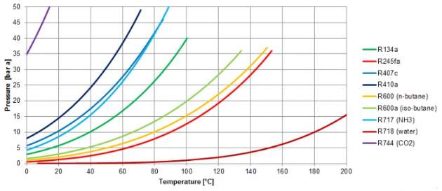
Figure 4
Critical Temperature
A refrigerant reaches its supercritical area above a certain temperature. Within this supercritical range, the fluid and gaseous phases can no longer be distinguished. If a refrigerant’s critical temperature is too low, this might impact system performance since certain heat pump components work optimally with certain states of matter (ex: compressor with gas) at high temperatures
Energy efficiency
Efficiency of heat pump depends on several factors, including choice of refrigerant. Depending on the efficiency needed for a particular application, certain refrigerants can be used.
Natural vs. Artificially Created
Most artificially created refrigerants contribute strongly to the greenhouse effect in case of leakage. Environmental regulations have to be considered while selecting refrigerant choice, especially when refrigerant leakage can have disastrous consequences for the environment.
The following is a summary chart for several frequently used refrigerants in heat pumps:
| Type | Characteristics | Applications |
| R134a |
|
|
| R407c / R410a |
|
|
| R600 / R600a |
|
|
| R717 (Ammonia) |
|
|
| R744 (CO2) |
|
|
| R718 (Water) |
|
|
Pressure-Enthalpy Diagram
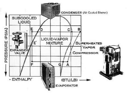
Figure 5
The pressure-enthalpy diagram determines thermodynamic properties for the refrigerant in the system and determines equipment performance. The region left of the saturation curve is known as compressed or subcooled liquid. If a refrigerant liquid is in this region, it is at a temperature that is cooler than the equivalent saturated temperature for the corresponding pressure. If a liquid falls on the left side of the saturation curve line, it is a saturated liquid- a liquid that is at the boiling point but has not begun to boil. The region within the dome is the saturated liquid-vapour mixture. Refrigerant within this dome exists in a saturated mixture of both vapour and liquid. Adding heat to a saturated liquid vaporizes part of it and makes it a saturated liquid-vapour mixture. If the liquid falls on the right side of the saturation curve line, it is said to be a saturated vapour. This state is attained by evaporating all of the liquid. Adding any more heat to the vapour will push it to the region right of the saturation curve, also known as the superheated vapour region.
In Figure 5, the refrigeration cycle is represented by G, A, B, D, E and F. The final temperature at the end of compression is dependent on the refrigerant and compressor efficiency. This cycle is more realistic than the theoretical vapour compression cycle. It shows that the vapour leaving the evaporator is superheated (i.e. past the saturation curve line, G to A) and the liquid leaving the condenser is compressed (D to E). Superheat ensures that no liquid arrives at the compressor where it could cause damage. Likewise, sub-cooling ensures that fluid flowing through the expansion valve is 100% liquid instead of saturated liquid, which could potentially cause pressure drop and reduction in system performance. The refrigerating effect per unit mass flow rate can be calculated by measuring enthalpic values between points F-A and compression energy A-B.
Types
There are two main types of heat pumps: air-source pumps and ground-source pumps. While air-source pumps work by transferring heat through air, using a cycle of evaporation and condensation, ground-source pumps transfer heat through earth or water
Ground Source Heat Pumps
Ground source, or geothermal, heat pumps (GSHP) use earth or water as a source of heat. Water is an ideal heat source; some heat pumps are therefore located nearby lakes or seas. Water is circulated through a coil submerged in the lake to the evaporator in the heat pump. As it circulates through the coil, it extracts heat from the water source so that it arrives at the evaporator in the pump at a temperature close to the lake/sea temperature. Lake or ground water is circulated rather than fed directly to the evaporator due to negative effect of contaminants. A common way of extracting heat is to circulate a glycol solution through plastic pipes, laid in trenches, and the ground source. Another way of extracting heat is to dill a bore hole and to circulate brine (i.e. salt water) to sufficient depth. GSHPs capture solar heat stored in the ground. While it is possible to circulate refrigerant directly through the ground, there is always the ever-present danger of underground refrigerant leakage.
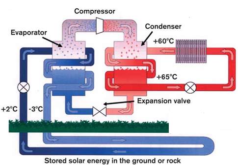 Figure 6 shows the inner workings of a GSHP. A cold water glycol mixture is pumped through the ground in a series of energy-absorbing pipes called ‘ground arrays.’ The anti-freeze water mixture is constantly kept warm by the ground’s low-grade heat. The anti-freeze mixture, having gained heat as it travels from outside to indoors, is fed into a heat exchanger known as the ‘evaporator.’ Liquid refrigerant is located within the secondary seal side of the evaporator. Energy, in the form of heat absorbed from the ground, is transferred to the refrigerant, which begins to boil and turn into gas. The refrigerant and water-glycol mixture is kept separate by the heat exchanger plates, which solely permit energy transfer. Refrigerant, in its gaseous state, then travels to a compressor, which increases the pressure and the temperature of the refrigerant gas. The hot refrigerant gas then flows to the condenser, which features an identical set of heat transfer plates as the evaporator. The condenser supplies water hot enough to serve the space heating system. The refrigerant, having transferred its energy to the water, condenses into a liquid. The liquid refrigerant passes through an expansion valve that further reduces its temperature and pressure before making its way to the evaporator. Air-Source Heat Pumps
Figure 6
Air- source heat pumps (ASHP) obtain heat from the outside air during the heating season and release heat outside during the summer cooling season. Typical ASHPs are like GSHPs in design, but with an air coil evaporator and fan instead of a plate heat exchanger and water pump. The mechanism of an ASHP is similar to that of a GSHP. Air-source heat pumps can be add-on, all-electric or bivalent. Add-on heat pumps can be thought of as external devices meant to be used with traditional methods of heating or cooling, such as oil, gas or electric furnace. All-electric air-source heat pumps contain their own form of electric-resistance heaters. Lastly, bivalent heat pumps use gas or propane fired burner to increase air temperature entering the outdoor coil. The units can therefore operate at lower outdoor temperatures.
There are two types of air-source heat pumps: air-to-air heat pumps and air-to-water heat pumps. Of these two, the air-to-air heat pump is more common. It obtains heat from the air and then transfers heat to either inside or outside the house depending on the season.
The air-to-water heat pump is used in conjunction with hydronic heat distribution systems. During the heating season, the heat pump draws heat from the outside air and then transfers it to the water in the hydronic heat distribution system within the house. With cooling, the process is reversed; the heat pump extracts heat from the water in the distribution system and releases it outside to cool the house.
Air source heat pumps have three cycles: the heating cycle, the cooling cycle and the defrost cycle. The defrost cycle is activated when the outdoor temperature falls to near or below 0˚C when the heat pump is operating in heating mode. Moisture in the air passing over the outside coil will condense and freeze on it. To remove frost, the heat pump will activate this mode. To do this, the reversing valve switches the device to cooling mode, which sends hot gas to the outdoor coil for release to the outdoor coil. At the same time, the outdoor fan is shut off in order to reduce heat needed to melt the frost. While this happens, the heat pump cools the air in the ductwork. The heating system warms this air as it is being distributed throughout the house.
There are some drawbacks with air source heat pumps. Capacity and efficiency is largely dependent on outdoor temperature. Severely low outdoor temperatures can result in problems such as poor performance, reduced pump efficiency and formation of ice on the outdoor coil, which may take a while to thaw in defrost mode. This is why air source heat pumps are not recommended for use in regions experiencing extremely low temperatures. The temperature to which heat has to be raised depends on the required temperature at point of use and the distribution system.
Applications
Due to their versatile nature, heat pumps have many residential and commercial applications.
Residential Applications
One of the best examples of heat pump applications is the refrigerator. The working principle of refrigerators and heat pumps is the same. In a refrigerator, heat removed from low temperature body (Q2) is desired; in heat pump, heat provided to the high temperature body (Q1) is desired. Heat is withdrawn from inside a refrigerator (low temperature), which reduces internal temperature of the refrigerator. This heat is given off to the environment (higher temperature). Modern refrigerators use a special type of refrigerant called HFC-134a as working fluid. This refrigerant is harmless to the ozone layer and is environmentally safer than alternatives used in the past.
Industrial Applications
Heat pump systems have a big place in industry. Due to their effectiveness in heating and cooling spaces, they are used across a variety of different industries.
In the petroleum refining and petrochemicals industry, heat pumps are used in the distillation of petroleum and petrochemicals products in processes such as separation of propane/propylene, butane/butylene, and ethane/ethylene. This is achieved by adding a heat pump to a traditional distillation column. Figure 7 compares the features of a distillation plant with heat pump to a conventional unit. With the addition of a heat pump to the apparatus, the reboiler and condenser are connected.
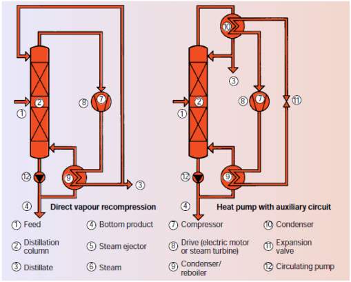
Figure 7
The heat pump increases existing energy in the column head, normally dissipated, and transfers it into the reboiler, where vapour is condensed. This process requires a fraction of the thermal energy of a conventional distillation process. Furthermore, it does not require any heating steam or large quantities of cooling water. Lastly, by adding a heat pump, the duty of reboiler and condenser is reduced, which is a sign of improved efficiency and thus saves a lot of energy.
In the Chemical Industry, heat pump systems are used to concentrate salt solutions and refine sugar. When it comes to sugar refining, large amounts of water must be evaporated from dilute sugar solution before final crystallization of the sugar. Figure 8-A shows the process being achieved by a standard multi-effect evaporator versus the same process being achieved by the more efficient typical mechanical vapor-compression evaporator (Figure 8-B). In the standard process, steam is supplied to the first effect to boil off some water and create vapor. After transferring its energy in the form of heat to the water in the dilute sugar solution, the steam condenses and exits the effect as steam condensate. The vapor from the first effect flows to a heat exchanger in the second effect, which operates at a lower pressure because of a vacuum applied to it. Some of the first effect vapor condenses while heating the solution in second effect, and escapes the second effect as process condensate. Concentrated sugar solution is extracted at the end of the process. Using a typical mechanical vapor-compression evaporator, work required to heat the solution is significantly reduced. A vapor compressor with a motor is connected to the effect. Process vapor exiting the effect flows to compressor inlet and is compressed into hot, high-pressure gas that condenses against the liquid being evaporated. The cost to drive the mechanical compressor evaporator is less than that of the cost of steam that drives the multi-effect evaporator.
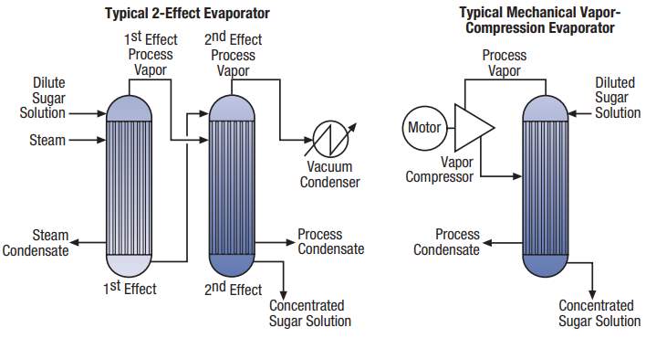
Figure 8-A
Figure 8-B
Another important application of heat pump systems is in the pulp and paper mill industry. Heat pumps can be used in lumber drying in the manufacturing process. Lumber is typically dried by supplying heated air to stacked lumber in an enclosed space. Fresh air is heated and supplied to a steam-heated lumber kiln. The hot air evaporates moisture from the lumber, which reduces its temperature. The cooler, moist air is returned to the atmosphere. This process takes time and is economically inefficient due to the high cost of suppling steam to the kiln A closed-cycle mechanical heat pump is used to improve efficiency of the drying process. The moist kiln air flows through the evaporator, which cools the air and produces some moisture condensation. The compressed heat-pump working fluid condenses against incoming fresh air, thus supplying hot air to the kiln. The cost of power to drive the heat pump is significantly less than that of using steam in the kiln without the heat pump. Figures 9-A and 9-B show the differences between standard and closed-cycle heat pump application process.
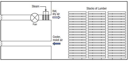
Figure 9-A
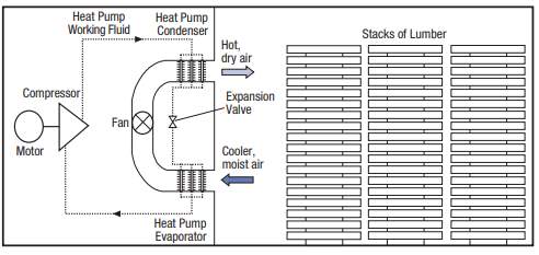
Figure 9-B
Heat pump also has several applications in the Food and Beverage Industry. One such application is the pasteurization of milk. Pasteurization, which aims at killing organisms in milk to lengthen milk shelf life, works by bringing in cool milk, heating it, before finally cooling it down again. A conventional pasteurizer brings in milk at 10˚C and preheats it to 62˚C with regenerative heat from pasteurized milk that is being cooled down. After preheating, the milk is heated to 72˚C using a hot water circuit typically powered by steam. After this desired pasteurization temperature is attained, milk needs to be cooled back down to 10˚C. Cooling is initially provided by fresh milk at 10˚C.The pasteurized milk is cooled to around 15˚C. Further cooling is provided with a cold water circuit powered by a mechanical cooling system. This system dumps the waste heat at its condenser site. Figures 10-A show this process.
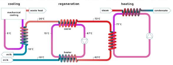
Figure 10-A
Application of an add-on heat pump allows the re-use of waste heat from the mechanical cooling system in the pasteurization process. Using the heat pump enables the process to run without the need for steam to heat the milk. Compressed gases from the refrigeration installation have a condensation temperature of 25-30 ˚C. The gaseous refrigerant passes through the heat pump compressor, which increases the pressure and hence, the condensation temperature (>80 ˚C) Heating for pasteurization comes from the heat released by the gaseous refrigerant as it flows through the condenser and has its heat released. Its pressure is then reduced inside an expansion valve after which it is sent back to the original cooling cycle. Figure 10-B shows this process.
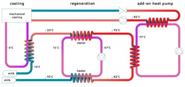
Figure 10-B
The following is a chart summarizing other applications of heat pump systems:
| Industry | Manufacturing Activity | Process | Heat-Pump Type |
| Miscellaneous | General manufacturing | Space heating | Mechanical Compression, Closed cycle |
| Utilities | Nuclear power | Concentration of nuclear waste | Mechanical vapor compression, open cycle |
| Chemical | Pharmaceuticals | Process water heating | Mechanical compression, closed cycle |
| Wood Products | Paper Manufacturing | Flash-steam recovery | Thermocompression, Open cycle |
| Food and Beverage | Manufacturing of alcohol | Concentration of waste liquids | Mechanical vapour compression, Open cycle |
Advantages and Disadvantages
| Advantages | Disadvantages |
| Lower running costs | High upfront cost |
| Less maintenance in the long run | Fairly challenging to install and set-up |
| Safer than combustion-based systems | Not designed for extremely cold temperatures |
| Reduction of CO2 emissions | High amount of electricity required |
| Long life-span | |
| Government rebates |
Advantages
Heat pump systems boast lower running costs than combustion-based systems. The more energy efficient the system, the greater the savings on energy usage. Heat pump systems also require less maintenance than combustion heating systems. If inspected by the home owner, the health of the system needs to be monitored periodically during the year to ensure systems are running optimally. If a professional installer is brought in, then the system needs to be checked every three to five years. This is better than combustion-based and electrical systems that may experience frequent breakdowns and issues. Heat pumps are also safer than combustion-based heating systems; unlike combustion-based heating systems, there is no worry of pipe leaks and explosive/flammable hazards. In terms of their effects on the environment, heat pumps reduce carbon emissions and have an efficient conversion rate of energy to heat. Some heat pump types are more efficient than others (ex: water source heat pumps, which reach high efficiencies). Air pumps are also capable to providing cooling in the summer months Air to air heat pumps can be switched to cooling mode with a press of a button during summers, thus acting as both air conditioning and heating units. Heat pumps are designed to have long life spans of up to 50 years, with average life span clocking in around 15 years. They are highly reliable and provide a steady source of heat. Lastly, the high upfront costs and running electricity costs of a heat pump can be mitigated with government assistance. Recently, the federal government was offering a tax credit up to 30 percent of the price of a geothermal pump through 2016. Furthermore, many states offer direct rebates for switching from a furnace system to a heat pump system.
Disadvantages
One of the biggest disadvantages of heat pump systems is the high upfront cost to purchase the unit. An air-to-air system for a single room in a residence starts at $500, while house units typically run in the range of $2000-$8000, including installation. The price of the systems is dependent on factors such as the home size (square footage) and the heat pump’s ratings. It is important to note that more expensive units tend to have higher energy ratings; the savings in energy bills over a long term will offset the large upfront cost. It is also important to note that heat pumps can be fairly challenging to install and set-up. Every home is unique, along with the area that it is in. Research needs to be conducted first to see whether the movement of heat, local geology (i.e. for ground source heat pumps) and household heating and cooling preferences meet the requirements for a residential heat pump system. There have also been a growing number of concerns with respect to the refrigerants used in these systems. Some artificial refrigerants that have been used in industrial heat pumps have been blamed for being toxic to the environment and posing the risk for leaking. A big issue with heat pumps is that they are not designed to operate in extremely cold temperatures. Efficiency of the pumps is reduced with temperature, thus full heat pump efficiency cannot be reached in the cold weather. This can be combated with an upgraded heat pump system that tackles this problem or using an add-on heat pump system alongside a conventional combustion-based furnace for the colder months. This also limits the use of heat pumps to geographical areas with warm to mild temperatures. Lastly, heat pumps require electricity to operate (i.e. electricity costs) and because of this, will be never entirely be carbon neutral. If used with solar applications, however, heat pumps could result in a small net energy (i.e. close to zero net carbon emissions)
Efficiency
The most used parameter to quantify efficiency of refrigeration and heat pump systems is COP, which stands for ‘Coefficient of Performance.’ The equation for COP is:
COP =
QW
Q is the useful heat supplied to the system or removed by the system under consideration and W is the work required by the system. The COP of a refrigerator is calculated using the following equation:
COPR =
Desired OuputRequired Input=
Cooling EffectWork Input=
QLWnet,in
The COP of a heat pump is calculated using the following equation:
COPHP =
Desired OuputRequired Input=
Heating EffectWork Input=
QHWnet,in
Note that both COP values can be greater than 1. Combining the two equations yields the following formula:
COPHP = COPR + 1
COPHP can be greater than 1 (100%) since refrigeration and heat pump devices move heat rather than creating it; heat moved can be higher than input work, resulting in COP of greater than 1. Because of this, heat pumps can be more efficient than simply converting input work into heat, as in the case of an electric heater or furnace. Theoretically speaking, if COPR is 0, COPHP will be 1, which means that, at the very least, it will supply as much energy as it consumes. In reality, however, some of QH is lost to the outside air due to factors such as insulation, piping and leaks, which cause COPHP to fall below 1 when outside air temperature is too low.
COP for an ideal refrigeration cycle is calculated with the following formula:
COPR =
TLTH-TL
COP for an ideal heat pump cycle is calculated with the following formula:
COPHP =
THTH-TL
Qh indicates how much more the heat transfer by the heat pump is than the work put into it. For example, a Qh of 5.30 means that heat transfer by the heat pump is 5.30 times as much as the work put into the system. Real heat pumps do not perform as well as this, however. The values of COPhp for heat pumps typically range from about 2 to 4. This means that heat transfer Qh from the heat pump is 2 to 4 times are great as the work put into them. However, the fact that these devices run on electricity limits their economical feasibility; W is usually supplied by electrical energy that costs more per joule than heat transfer by burning fuels such as natural gas. Values of COPref for air conditioners and refrigerators range from 2 to 6. These numbers are better than COPHP because temperature differences are smaller.
The COP ratio is heavily dependent on operating conditions such as temperature and flow, which makes it less than ideal for gauging efficiency of heat pump and refrigeration systems. In recent years, the system efficiency index (SEI) has been proposed as a better parameter to gauge heat pump efficiency. The system efficiency index (SEI) was developed by German Engineering Federation (VDMA) and the Institute of Refrigeration (IOR) by first defining what a 100% efficient process between desired temperature levels (i.e. TL and TH) would achieve. The Carnot COP is a reference for a process that transfers heat energy to higher temperature level and is consistent with the thermodynamics laws. Measured COP is compared with ideal COP, resulting in efficiency that varies less with external operating conditions such as flow and temperature. The formula for SEI is given as follows:
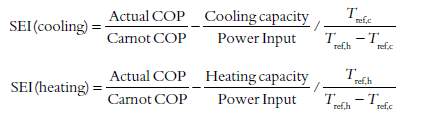
Tref,h and Tref,c are secondary fluid temperatures at the reference conditions. It is common to use median or mean values for these temperatures wherever possible. For secondary flows in condensers and evaporators, for example, this would suggest using mean temperature of fluid entering and exiting. Due to difficulties in measuring temperatures, the entering fluid temperature is typically used.
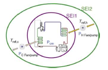 Figure 11 illustrates the concept of system boundaries, where SEI1 refers to the process itself and SEI2 accounts for power input to the fans and pumps that are required to run the cycle. This power is the power required to circulate air or other fluid through the refrigerant heat exchangers.
Figure 11
The System Efficiency Index is a product of sub-efficiencies, which are efficiencies of various components within the refrigeration process. These components include the following:
- Refrigerant Cycle: Accounts for the non-ideal nature of the cycle with design choices such as particular refrigerant used, use of an economiser and materials used to build the device.
- Compressor Efficiency: Accounts for compressor losses. For cooling cycle, this is the compressor isentropic efficiency (IE)
- Heat Exchanger Effectiveness: Accounts for condenser and evaporator temperature differences between primary and secondary flows and heat exchangers effectiveness
- Pressure drop: Accounts for power used to circulate refrigerant through pipes. Affects large systems with long pipes.
- Auxiliary loads: Accounts for pump and fan power
- Fluid Transfer Efficiency: Accounts for fluid effectiveness and includes ‘non-useful’ heat pick-up
In the United States, the Energy Star Rating system is used, one that is based on the COP rating system called the “energy efficiency rating” (EER) is used. The Energy Star Rating is out of 5 stars- the more stars, the more energy efficient the device. EERs are expressed in
Btu/hrW. The EER of an air conditioner or refrigerator can be expressed as:
EER =
QcT1WT2
Discussion
When discussing strategies at optimizing heat pump performance and increasing its efficiency, three aspects of the overall process from start to finish (i.e. manufacturing to use) must be discussed: design of the heat pump, installation of the pump and maintenance
When considering system design, attention must first be paid to ensure that load is an absolute minimum. Since an efficient system is built with a load in mind, it is necessary to first determine what this load is and how much of it can be reduced. Load elements are elements such as heat input from auxiliary equipment, lighting, heat conduction and direct solar radiation. This requires a critical energy survey of the residence to be outfitted with a heat pump system. The purpose of this survey is to identify the different elements of the cooling and heating loads and strategies of reducing each item to a minimum. If the place of residence permits heat conduction through building structure, better insulation should be used. If there is direct sunlight into the cooled space, shading or window tinting options should be considered.
Free cooling can be used to offset a portion of the load. Referring to a method that does not require mechanical refrigeration but rather wet-bulb temperature to be below required temperature level of cooled space, free cooling is another strategy at increasing system efficiency. If the heat pump is in cooling mode, then a design choice to consider would be to pre-cool water for circulation in the building prior to being cooled by the refrigeration process. A free cooling chiller air conditioning circuit can be built and implemented.
When considering system design, condensing pressure should be minimized and the evaporating temperature maximized. Loads should be split where separate cooling temperatures are required to avoid all compressors working at pressure corresponding to lowest load temperatures. For large temperature lifts, enhanced cycles should be considered, for example two-stage cycles that give better efficiency.
The system design should focus on making improvements to the operating conditions with high numbers of running hours. Fixed speed for auxiliary equipment such as pumps and fans should b avoided since pump and fan power should be reduced at low loads. Fixed set head pressure control should also be avoided to ensure low condensing temperatures.
Compressors and condensing units should be selected for normal running conditions, while possessing the capacity for design point. Evaporating units should be checked for evaporating temperature at which they operate. Temperature differences should be appropriately considered for choice of heat exchangers. Lastly, refrigerant appropriate to the application should be selected. The impact of refrigerant on efficiency is around 5%, assuming all other parameters are optimized.
When installing heat pumps, consideration must be given to the following points:
- Length of pipelines should not be too long. Excessively long pipelines can cause heat loss through pipes or pressure drop within pipes, which will affect system performance
- Water velocities
- Refrigerant velocities
- Water qualities
- Choice of wetted material
If given the choice of which air pump system to install, it is advisable to choose ground source heat pumps whenever possible. This, obviously, depends on the individual’s budget as well as factors such as air patterns, geological conditions and heating and cooling requirements of the household. Ground source heat pumps boast a higher COP than air source heat pumps since the ground is an excellent conductor of heat. Therefore, collecting heat from the ground and transferring it to the indoors coil and vice versa is easier since transfer of heat is much more efficient. If possible, it is advisable to use a ground source collection area that is saturated with water. This is because water is an excellent conductor of heat; placing collection coils in areas of the ground that are wet will help boost COP.
When installing the pump system, attention must be paid to the surface area of the emission and collection points. The larger the surface area, the faster the heat pump can achieve the desired indoor room temperature. An example of this would be installation of under-floor heating systems. More heat is released over a wider area, and the room quickly reaches the desired room temperature. Compared to electric and gas boilers, heat pumps have a much lower hot water temperature. Increasing the size of the radiators can help heat a room quicker. If under-floor heating systems are installed, then solid floors (i.e. tiles) should be installed. Wooden and laminated floors are poor conductors of heat and will be ineffective at heat transfer.
While installing the heat pump, it is advisable to check the residence for insulation. Poor insulation is a major cause of high energy bills, as inside air, whether cooled or heated, slowly leaks outside and the heat pump system needs to work that much harder to maintain the desired temperature. Areas such as window frames and door jambs (latch jamb, hinge jamb, head jamb and two-piece jamb) are at risk of being poorly insulated. Home owners are advised to ensure that these areas are properly insulated (e.g. use cocking to insulate area between windows and windowpanes from outside)
Older piping materials can lose a lot of heat when transferring fluids from a heat pump system. Pipes need to be upgraded to low temperature materials (i.e. materials with low thermal conductivity) Along with pipes, materials such as boards, blocks, blankets, strips and sections need to be considered for their properties. Excellent materials to use include: polystyrene foam, foam glass and mineral wool boards.
Once the heat pump system is installed and running, there are a few ways home owners can increase heat pump’s efficiency and cut their energy bills.
The first way of increasing the heat pump’s efficiency and reducing energy usage is to periodically change the air filter. Over time, an air filter traps pollutants such as dust, hairs and other contaminants, which impede air flow to the heat pump and force the system to work harder to keep the interior space cool or warmer. Air filters must be changed regularly, especially if there are pets in the household, or when it looks dirty. Energy Star, a subset of U.S Environmental Protection Agency, recommends changing the filter every month or at least once every three months, especially during the summer and winter months when the system works hardest.
The second way of improving efficiency is to maintain air ducts. This is done in two ways: by ensuring air ducts inside the residence are clean and checking ducts of the pump and within the residence are free from leaks and holes. The National Air Duct Cleaners Association recommends getting air ducts cleaned every three to five years. Because air carries with it pollutants such as dust, hair and other contaminants, some of these pollutants can make way into ducts and cause a build-up over time. This impedes air flow and reduces system efficiency. Care must be given to ensure that ducts are thoroughly cleaned of dust and other pollutants once every two-three years. Ducts that have leaks lead to high energy bills and difficulty in heating or cooling some areas in the house. Leaks and holes on ducts must be sealed using metal tape or mastic sealant. All connection points between ducts and ceilings, floors or walls must be sealed with duct or metal tape. A well-functioning duct system increases pump efficiency by ensuring that conditioned air is not lost during air distribution.
Servicing the heat pump every year can improve its efficiency. Thermostat settings need to be tuned, all connections tightened and all moving parts lubricated so as to minimize friction. It is also recommended that controls system is checked from time-to-time and set to the correct settings. Maintenance checks are highly recommended- it must be ensured that the heat pump starts, functions and goes off safely and properly, especially in the winter months. Homeowners are advised to check the blower system to correct any airflow problems, which, according to Energy Star, can reduce heat pump’s efficiency by 15 percent. It is advisable to service the pump in the spring or fall every year to help ensure optimal performance.
Lastly, using a programmable thermostat is an excellent way of saving energy and reducing residential energy demands. It allows the homeowner to adjust the indoor temperature according to settings that occur at different times of the day. For example, during the hot summer months, home owners can allow air temperature to rise when no one is home but turn on the air conditioning an hour before someone arrives. Furthermore, thermostat expansion valves direct air flow with higher accuracy to indoor coils.
Conclusion
In conclusion, there were quite a few strategies discussed to improve efficiency. There are three steps at which efficiency can be improved: When the heat pump system is being designed, when the heat pump system is being installed and periodic maintenance once the system has been installed and running. Improving efficiency at all three steps is key to improving the efficiency of the heat pump system and reducing energy usage. Not only does the system have to be designed with minimal load elements in mind, but the structure of the house itself has to be considered when designing and installing the system.
Recommendations
After looking at the different types of air pump systems, the recommendation for the heat pump type suited for most U.S residential homes is the add-on air-air source heat pump. Refrigerent 410A seems to be most suited for residential spaces, since it is designed for low temperature modes. It is recommended that the system be dual-cyclic as that will improve efficiency. Also, in colder regions of the States, this heat pump system can be used as an add-on to traditional furnace systems to ensure heating during the winter.
Appendix
Table # |
Description |
Pg. # |
1 A |
||
Cite This Work
To export a reference to this article please select a referencing stye below:
Related Services
View all


Related Content
All TagsContent relating to: "Energy"
Energy regards the power derived from a fuel source such as electricity or gas that can do work such as provide light or heat. Energy sources can be non-renewable such as fossil fuels or nuclear, or renewable such as solar, wind, hydro or geothermal. Renewable energies are also known as green energy with reference to the environmental benefits they provide.
Related Articles

DMCA / Removal Request
If you are the original writer of this dissertation and no longer wish to have your work published on the UKDiss.com website then please: