Mechanical Efficiency Prediction Methodology of the Hypocycloid Gear Mechanism
Info: 10116 words (40 pages) Dissertation
Published: 9th Dec 2019
Tagged: Mechanics
Mechanical Efficiency Prediction Methodology of the Hypocycloid Gear Mechanism for Internal Combustion Engine Application
Abstract
Mechanical friction power loss is one of the main concerns in the internal combustion engine (ICE) systems. The piston-rod assembly and the complex motion of the connecting rod are the largest source of engine friction. A significant reduction in these losses can be achieved with ICE systems by incorporating the hypocycloid gear mechanism (HGM), which ensures that the piston-rod assembly reciprocates in a perfect straight-line motion along cylinder axis. This paper investigates the feasibility of an enhanced hypocycloid gear mechanism (EHGM) for the design and development of internal combustion engine application. It incorporates designing the gear train to satisfy internal combustion engine loads and design specifications using the standard design procedures provided by AGMA. This is followed by building the friction model for the interacting components of the design through developing the mathematical model for power loss of planetary gear meshes, rolling bearings, and sliding bearings. The friction model was validated by selecting an engine from the market, designing the EHGM engine, then the total power losses due to friction was estimated. Afterwards, the friction model for the conventional crank-slider engine was introduced and analyzed for the same selected engine and then compared with the EHGM engine in terms of frictional power losses. The comparison results show the feasibility of using the EHGM design for internal combustion engine application with minimized engine frictional power losses and hence higher mechanical efficiency.
Keywords: Hypocycloid; Internal Gears; Friction; Power Loss; Internal Combustion Engines; Mechanical Efficiency
1. Introduction
The transmission of motion between the piston and the crankshaft has utilized the traditional crank-slider mechanism for its simplicity and efficiency and for this reason it has remained almost unchanged since its introduction. However, in the past and even nowadays, different mechanisms have been studied and analyzed because of their advantages over the crank-slider mechanism and the possible positive enhancements that can be achieved for better engine performance and higher efficiency. As an example for this effort is the sinusoidal engines, so named because the mechanisms incorporated allows the piston to move in sinusoidal straight-line motion. One of the mechanisms utilized with sinusoidal engines is the planetary gear-train mechanism. This mechanism is kinematically recognized as hypocycloid mechanism, since Hypocycloid is the term which describes the basic kinematic principle involved. Some literatures prefer using the term Cardanic but it is basically the same principle.
A hypocycloid is the curve generated by the trace of a fixed point, A, located on the circumference of a small circle of radius Rp that rolls without slipping along the inside of a larger fixed circle of radius Ro, as shown in Figure 1(a). This curve degenerates into a true straight-line, the diameter of the large circle, if the diameters of the large and small circles are in the ratio of 2:1, as shown in Figure 1(b). In fact, every point on the smaller circle now moves in a perfectly straight-line passing through the center of the large circle but at a different angle. If the large and small circles are the pitch circles for a fixed internal gear and a planet pinion gear, with a diameter ratio of 2:1, then the hypocycloid gear mechanism (HGM) is formed. As the planet pinion gear is rotated to roll on the inside of the fixed internal gear, the particular point A is chosen on the pitch diameter of the planet pinion gear, as shown in Figure 1(c), to provide a perfectly vertical straight-line path. If the bottom of the connecting rod is attached to point A to trace its straight-line path shown in Figure 1(c), it will provide the basis of a possible replacement for the crankshaft with a planetary crank gear mechanism to provide means whereby the piston and the connecting rod are caused to travel along a straight-line axially of a cylinder. This form of the mechanism is recognized as the basic HGM.
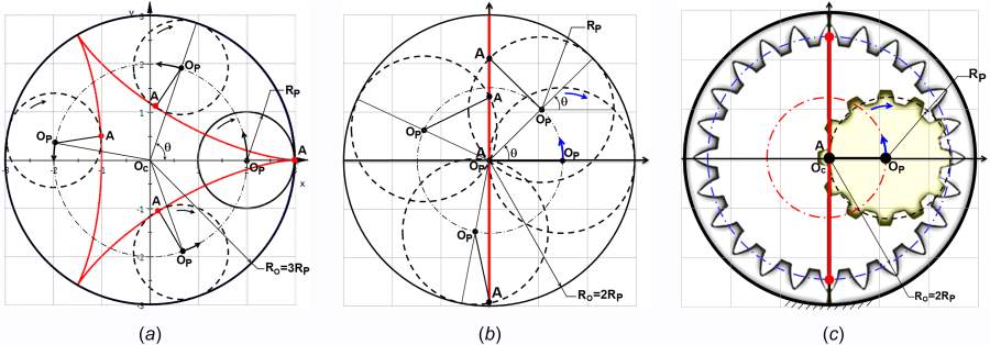
Figure 1 Principles of hypocycloid motion to develop an HGM engine
Such a mechanism provides several characteristics which makes it attractive for internal combustion engine application. The piston motion to start with is purely sinusoidal relative to crank rotation angle, as opposed to the motion produced by a conventional crank-slider mechanism. This would be beneficial for achieving perfect engine balance for any number of cylinders. The straight-line motion of the piston and connecting rod would eliminate the need for the wrist pin bearing which allows for a very short piston without concerns of chocking occurrence. Also, this motion should eliminate the piston side thrusting into the cylinder walls which would allow for minimizing piston friction losses, eliminating the piston skirt, and preventing the piston slap occurrence even with large piston-cylinder clearance. The elimination of side thrusting forces would also result in increased engine output power, which would allow for smaller engine displacement, hence smaller cylinder length, with the advantages of lower engine weight, size, and cost.
The mechanism characteristics briefly mentioned above shows that HGM engine might have significant advantages over conventional crank-slider engine. Despite these advantages, the mechanism would be beneficial only if it can be shown to handle engine loads and speeds for a modern internal combustion engine, and to be manufactured within a reasonable size at a reasonable cost. Several attempts were carried out for applying this concept with internal combustion engine applications, some of these attempts in the last thirty years are shown below in a chronological order.
The concept of hypocycloid engines is quite old that [1] presented a complete comprehensive summary, to its date, for the design and its variations that have appeared over the years and the limited developmental work that was done. They showed many inventions and patents claiming the applicability of such mechanism in applications for steam and internal combustion engines. They first introduced the potential advantages for applying HGM concept specially with small single cylinder applications. Then they investigated the engine performance including considerations for breathing and combustion, load analysis for gears and bearings. They finalized the study with a main conclusion of considering gears as the critical part of the design concept and care should be provided for gear design procedure. Few years later, they came up with an improved design shown in [2], where the modified design incorporated a sun gear fixed on the crank shaft while having a movable pinion and internal ring gear. Despite the pinion and the gear are larger than half the stroke and the stroke respectively, the straight-line motion is successfully maintained. This modification allowed for reducing the load on gear tooth and crank pin as compared to the basic HGM design. However, the use of more gears has slightly decreased the efficiency of power transmission.
The fact that the connecting-rod’s motion is in perfectly straight-line was made use of by [3], where the lower portion of the cylinder was utilized as a second working chamber. They ran experimental tests on two prototypes, one for a double acting reciprocating compressor and the other for two stroke spark ignition engine with the scavenging pump separated from the crank case. Despite the compressor results showed large increase in the mechanical efficiency as compared with single acting compressors, some difficulties appeared with the two stroke spark ignition engine, particularly with the sealing between lower chamber and the crank case, in addition to the design and construction of gears and bearings, and suggested lubrication mechanism. In line with that idea, [4]applied a similar concept but to a parallel combustion two stroke engine. He made use of the previous idea of having two chambers in the working cylinder, but then connected them with combustion chambers external to working cylinder. The new cycle consisted of five distinct functions, each defined by a full piston stroke without the function overlap common in existing two stroke engine. This idea combined most of the advantages of four stroke engine and external combustion engines into a two stroke engine.
A comprehensive analysis for the basic HGM engine design was carried out in the PhD dissertation of [5]under two applications, air pumps and four stroke engines. He assessed the old cardan gear mechanism (basic HGM) against the conventional crank-slider mechanism. He carried out a comprehensive investigation and a comparison between the two mechanisms in terms of the kinematic characteristics, the inertial forces included, thermodynamics, torques and power output, the total frictional losses, and total mechanical efficiencies. He came to the conclusion that, due to the good mechanical efficiency achieved, the cardan mechanism is worth utilizing with pumps and with four stroke engines for better energy savings. He finalized the dissertation with preliminary design guidelines to be used for cardan gear machines. Few years later, the engine proposed by Wiseman Technologies Inc. incorporating the basic HGM arrangement was investigated by [6]. They used Lotus Engine Simulation software for modeling engine specifications and simulating engine performance which was later then compared with experimental tests carried on a prototype (WHE alpha) for the engine. They did further simulations on the diesel four stroke version of the engine and did some analysis on the fuel efficiency. Their results showed confirmation between simulations and the experimental testing, and the resulting engine performance showed promising results for torque and power output as compared to the conventional crank-slider engine.
An enhanced version of the hypocycloid gear mechanism (EHGM) engine was introduced recently in [7] and [8] with a main objective of improving the combustion characteristics. It was aimed for improving the efficiency of the internal combustion engine through allowing for true constant volume combustion which in turn would lead to higher work output. The simulations carried out for the enhanced design were shown to achieve higher in-cylinder pressure, near constant volume combustion at top dead center (TDC) and more air charge time at bottom dead center (BDC) as compared to the conventional crank-slider engine. This came along with the improved performance over even the basic HGM engine in kinematic characteristics and torque output.
In continuation for this work done on EHGM, this study is aiming for modeling and analyzing the frictional losses of the components incorporating the EHGM engine, then compare the performance of the enhanced design with the conventional design in terms of frictional power loss. So, first the authors will be introducing the EHGM engine design as described in their previous work. Second, they will show the recommended standard design procedures for the challenging components to satisfy the engine load characteristics required. Third, they will build the friction model required to predict components frictional power losses in the enhanced design. Finally, a comparison will be carried out between the enhanced design and the conventional one to validate the EHGM engine frictional power loss.
2. Development of Hypocycloid Gear Engine
Engine development is divided into two stages; first, the basic HGM engine, then second, the enhancements. Figure 2 shows the detailed design of the planetary crank gear system that is utilizing the principle of the HGM for one-cylinder engine.
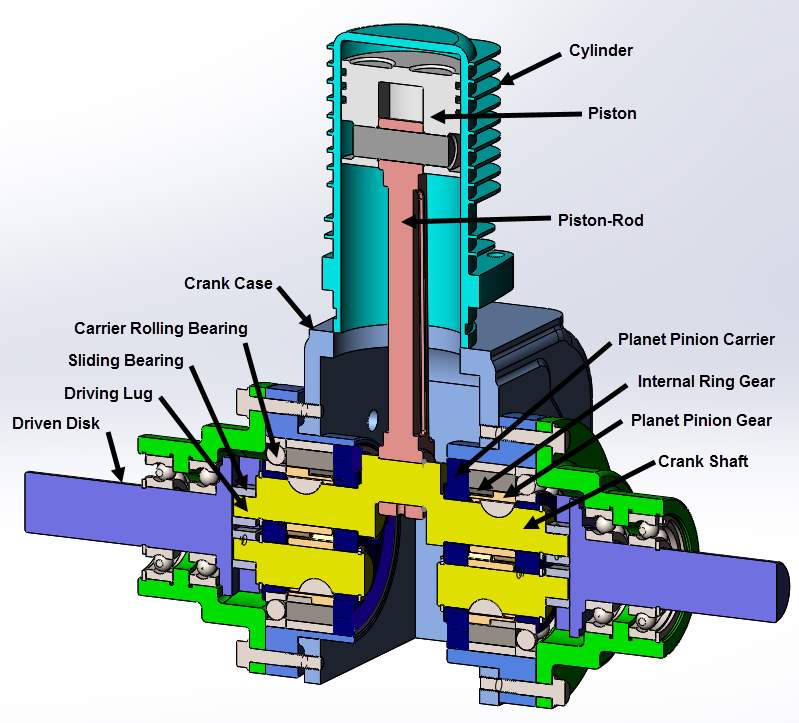
Figure 2 Sectional assembly view of the single cylinder and associated HGM assembly
First, Basic HGM Engine
It consists of two identical gear sets mounted back-to-back, with enough space between them to allow room for the crank pin. The space between these two gear sets is for the crank pin that is journalled within one end of the connecting rod. The other end of the connecting rod is attached to the bottom of the piston by a joint. Each gear set consists of three basic components commonly known as, an internal ring gear, two planet pinion gears, and a planet pinion carrier, respectively. The internal ring gear is attached to the crankcase portion of the engine block and does not rotate with respect to the other rotating members. The two planet pinion gears simultaneously rotate around their axes and revolve around the axis of the gear set along the inner circumference of the internal ring gear. They are mounted 180° apart from each other and also offset axially to prevent the gear teeth from interfering with each other. The center line of the crank pin journal is directly in line with the pitch circle of the planet pinion. This effectively forms the appearance of a conventional crankshaft, as shown in Figure 2. The carrier is mounted on the inside of the rolling bearing which is allowed to rotate freely. The outer race of the rolling bearing is then fixed with the crankcase next to the internal ring gear. With this arrangement, as the planet carrier is rotated 360°, the crank pin journal reciprocates up and down in a perfectly linear motion across the pitch diameter of the fixed internal ring gear.
Second, EHGM Engine
Looking at the assembly from an end on view, as illustrated in Figure 2, extending from the end of the pinion shafts are the two smaller diameter stub shafts. The purpose of the stub shafts is to create driving lugs. The position of the center line of the driving lug is offset by driving lug offset (δ) from the center line of the pinion shaft. The direction of the driving lug offset is approximately opposite to the crank pin journal. The driving lugs with their sliding bearings are then indexed into a slot in a disk. This disk is then driven by the driving lugs. The shaft portion of the driven disk is supported by bearings which are mounted in the lower crankcase portion of the engine block. The power output torque of the engine is taken from the shaft portion of the driven disk. Since there are two complete planetary gear sets mounted back-to-back, there are also two driven disks and output shafts.
When the pinion shaft rotates, the driving lug orbits around the center of rotation of the pinion shaft. As the entire planetary crank assembly is rotated 360°, the path of the driving lug is an ellipse, which is defined as “with driving lug offset,” as shown in Figure 3. The dimensions of this path (r(θ), a, and b), calculated in equation (1), are determined by the stroke of the crank pin (LC) and the amount of offset of the driving lug (δ).
| rθ=aba2sin2θ+b2cos2θ | (1) |
For a zero offset (δ), the center lines of the pinion shafts will be coincident with the respective centerlines of driving lugs. As a result, the path of the driving lugs with no offset will be a circular path, and this is defined as “without driving lug offset.” The diameter of this circle is equal to half of the stroke length, as shown in Figure 3. To increase the effective moment arm offered by the crankshaft and control the rate of piston movement in a combustion zone, the center lines of the driving lugs are moved away from the respective center lines of the pinion shafts by the desired driving lug offset (δ). As a result, the path of the driving lug forms an elliptical orbit, as shown in Figure 3. Due to the fact that the polar radius of the elliptical orbit r(θ) varies from minor to major radii (a, b), the length of the semi-major axis will be the maximum moment arm offered by the crankshaft when the output shaft is at 90° after top dead center. This characteristic also provided a nonlinear rate of piston movement because of the elliptical path of driving lugs around the axis of the output shaft which caused the piston movement near the ends of a stroke to be slower to provide additional time for combustion operation.
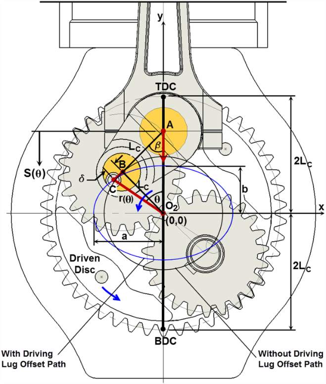
Figure 3 Kinematic Scheme of the HGM
Now, with the concept of EHGM clearly defined, the biggest concern about the mechanism was the ability of internal gear train to withstand internal combustion engine loads. So, the next section would handle this concern to ensure the mechanism is safe from strength point of view. Afterwards, the interaction between the engine elements should be assessed in terms of frictional losses to estimate the power losses of the EHGM engine.
3. Gear Design
There has been a great deal of work done over the years on determining allowable gear loads, and standard procedures have been developed. The most reliable set of procedures, the AGMA standard, will be used here. As the hypocycloid gear set dimensions (the diameter of the internal gear equals to the stroke length Se, and the pinion diameter is half of the internal gear diameter) are known, the gear set strength characteristics according to AGMA standards are then completely defined to be suitable to the engine size. Once the optimal gear geometry, in terms of gear stresses, is determined for one engine size, the maximum capacity can then be customized to the engine by changing the face width of the gear. If the face width would be too large, selecting helical gears should be considered.
Hypocycloid Gear Force Analysis
Because of the straight-line formed by the piston-rod motion, the gas force acting on the piston head (Fg) is aligned with the cylinder axis so that the tendency for the piston to move transversely and tilt is totally eliminated. The gas force is completely transmitted from the piston by the connecting rod to the crank pin center and causes the crankshaft to rotate. As the planet pinion rotates around the crankshaft axis and is in continuous engagement with the internal ring gear, the tangential gear tooth load on the planet pinion, given in equation (2), is found to be a function of the gas force and independent of the engine speed.
| Ftθ=FgθrθLC+δsinθ | (2) |
Gear teeth should be designed with a load carrying capacity satisfying equation (2). Due to the kinematics of EHGM engine, the peak tangential force does not necessarily occur at TDC as the peak gas force. So, gear teeth should be able to withstand the peak tangential force at any angular position of crank.
AGMA Design Equations
Gear design and analysis of AGMA standard design procedure available at[9] focus primarily on resisting bending failure of teeth as well as pitting failure of tooth surfaces. Failure by bending will occur when the significant tooth stress equals or exceeds either the yield strength or the bending endurance strength. A surface failure occurs when the significant contact stress equals or exceeds the endurance contact stress. The fundamental rating formulas used are applicable for rating the pitting resistance and bending strength of internal and external spur and helical involute gear teeth operating on parallel axes. Since there is no AGMA application standard specific for gears used in internal combustion engines application, numerical values may be estimated for the factors in the general formulas, and then the approximate pitting resistance and bending strength ratings are calculated.
Fundamental Rating Formulas for Pitting Resistance
The aim of the AGMA pitting resistance formula is to determine a load rating at which progressive pitting of the teeth does not occur during their design life. The Fundamental Formula for pitting resistance is given by equation (3).
| sc=CpWtKoKvKsKmdFCfI | (3) |
where sc is the contact stress number and Cp is the elastic coefficient. Ko, Kv, Ks, Km, and Cf are factors that consider gear overload, dynamic effects, gear size, teeth load distribution, and surface condition respectively. Wt is the transmitted tangential load and I is the pitting resistance geometry factor. The variables d and F are the operating pitch diameter and the face width respectively. The contact stress shouldn’t exceed the Allowable Contact Stress Number given by equation (4).
| sc≤sacSHZNKTCHKR | (4) |
where sac is the allowable contact stress number, SH is the safety factor for pitting resistance, and ZN, KT, CH, and KR are factors that consider gear pitting resistance stress cycle, operating temperature, gear pair hardness ratio, and design reliability respectively.
Also, the Pitting Resistance Power Rating given by equation (5) shouldn’t be exceeded by the transmitted power of hypocycloid gears.
| Pac=πnpF396,000IKoKvKsKmCfdsacCpSHZNCHKTKR2 | (5) |
where np is the pinion speed.
Fundamental Rating Formula for Bending Strength
The intent of the AGMA bending strength rating formula is to determine the load which can be transmitted for the design life of the gear drive without causing root fillet cracking. The Fundamental Formula for bending strength is given by equation (6) below.
| st=WtKoKvKsPdFKmKBJ | (6) |
where st is the bending stress number, Pd is the diametral pitch, Km is the rim thickness factor, and J is the bending strength geometry factor. Similarly, bending stress number shouldn’t exceed the Allowable Bending Stress Number given in equation (7).
| st≤satYNSFKTKR | (7) |
where sat is the allowable bending stress number, SF is safety factor for bending strength, and YN is gear bending strength stress cycle factor.
Like before, Bending Strength Power Rating given in equation (8) shouldn’t be exceeded by the transmitted power of the hypocycloid gears.
| Pat=πnpd396,000 KoKvFPdJKsKmKBsatYNSFKTKR | (8) |
Geometry Factors
It is recommended that geometry factors, I and J, used in the fundamental rating equations to be determined using[10]. It includes tables for some common tooth forms and the analytical method for involute gears with generated root fillets if manual calculation is desired.
For Pitting Resistance Geometry Factor (I), it evaluates the radii of curvature of the contacting tooth profiles based on tooth geometry. It is given by equation (9).
| I=cosϕrCψ21ρ1±1ρ2dmN | (9) |
where the ± sign here and afterwards is to indicate external gearing (+) and internal gearing (–), φr is the operating pressure angle, Cψ is the helical overlap factor, ρ1, 2 is the curvature radius of pinion/gear tooth profile respectively measured at the point of contact stress calculation, and mN is the load sharing ratio.
For Bending Strength Geometry Factor (J), it evaluates the shape of the tooth, the position at which the most damaging load is applied, and the sharing of the load between oblique lines of contact in helical gears. Both the tangential (bending) and radial (compressive) components of the tooth load are included. The formula used in equation (10) applies to external gears only.
| J=YCψKfmN | (10) |
where Y is the tooth form factor, Kf is the stress concentration factor.
For internal gears, the models presented in Annex A of [11] and in [12] will be utilized. The analysis presented there is for spur gear meshes only. However, for helical gears, the analysis should be considered preliminary where it can serve as the starting point for a detailed finite element analysis afterward.
The main idea is that it is required to determine the size of the largest inscribed parabola in the internal gear tooth. Based on the size of this parabola, the geometry factor is established. It can be calculated using equation (11) for any tooth section.
| J=1Ktcosϕncosϕ1.5X-tanϕnt | (11) |
where Kt is the stress concentration factor, calculated as shown in equation (12), φn is the tooth normal force angle measured at the highest point of single tooth contact, φ is the pressure angle, X is the ratio between tooth thickness, t, and height, h, measured at the critical section, and is given by equation (13).
| Kt=H+trfLthM | (12) |
where constants H, L, and M in equation (12) are function of the pressure angle, and rf is the root fillet radius of the tooth.
| X= t24h | (13) |
To find the point where J is a minimum, an iterative procedure is carried out utilizing equations (14 and 15) below for h and t which are calculated as a function of the general radius, A.
| h=±Rx∓Acos1±12πNG∓α | (14) |
| t=2Asin1±12πNG∓α | (15) |
where Rx is the radius to point of application of the worst load, NG is the number of teeth, and α is the angle of gear tooth measured at the general radius A.
To validate the design, the surface and bending stress values for the pinion and the gear should be below the allowable stress values calculated. The transmitted power through gears should also be lower than the surface and bending allowable power rating calculated. Once satisfied, therefore the planetary gears used are ensured to withstand the engine loads. Then the following step would be, based on the size of the planetary gears (diameters and face width) and the gas force generated, we can select the carrier rolling bearing required and then start analyzing the friction between interacting surfaces.
4. Friction Losses
The EHGM engine has an increased number of friction interfaces compared to a conventional crank-slider engine due to additional bearings and gear meshes. Thus, the frictional behavior for these components is an important issue to take care of in total EHGM engine frictional power losses. In this section, frictional power loss models will be developed for gear meshes, rolling bearings, and sliding bearings respectively.
1st Gear Mesh Losses
Since gears are the primary power transmission component in this design, power losses caused by the gear set is critical to the overall power transmission efficiency.
Classification of Power Losses
Power losses in any geared transmission can be classified into two main categories[13], [14]: load-dependent (mechanical) power losses and load-independent (spin) power losses. Load-dependent power losses result from the relative sliding and rolling action of an elastohydrodynamic lubricant film between meshing teeth. Load-independent power losses can result from the drag of rotating components and pocketing of lubricant at the gear mesh interface. Depending on the input power and speed, lubricant characteristics, and crank case design, the load-independent gear power losses usually are a very important source of power loss. Due to an almost infinite combination of crank case design choices and operating conditions, it is very difficult to develop a simple and general formulation to evaluate these power loss mechanisms. So, the gear set load-independent power loss needs to be measured from experimental observations for reliable power loss values.
Mechanical Losses
The mechanical power loss calculations for the geared hypocycloid engine design with pinion/internal gear pair can utilize the Ohlendorf method and the Velex et al. method. These methods are known to be applicable with planetary gear trains, so both external and internal gearing power losses can be assessed.
Ohlendorf Equation – Gear Loss Factor
Ohlendorf equation as reported in [15] and [16] introduced an approach for the load-dependent losses of internal gears. The power loss generated between gear tooth contact can be calculated according to equation (16).
| PVZP=PINHVµ | (16) |
where PVZP is the load-dependent gear power loss, HV is gear loss factor, and μ is the coefficient of friction. The gear loss factor according to Ohlendorf can be calculated as shown in equation (17).
| HVohl=u±1uπz11cosβb1-ϵα+ϵ12+ϵ22 | (17) |
where u is the gear ratio, z1 is the pinion number of teeth, βb is the helix angle measured at the base circle, ∈α is the transverse contact ratio, and ∈1, 2 are the addendum/dedendum contact ratios respectively.
Velex and Ville Equation
The equation developed by Velex et al. in [17] and [18] in order to calculate the efficiency of a meshing gear pair, obtained a closed form solution for the efficiency of a meshing gear pair, as presented in equation (18).
| ρ=1-μu±1uπz11cosβbϵαΛμ | (18) |
where ρ is gear pair efficiency and Λ(μ) is a dimensionless loss factor calculated as given in equation (19).
| Λμ=2ko2-2ko+11-μtanαt2ko-1-πz1ϵαko2-2ko+1cosβb | (19) |
where Ko is a dimensionless factor related to pitch point position on base plane and αt is the pressure angle. The factor Ko can be calculated using equation (20).
| Ko=z1u2πϵα ±ra2rp221cos2αt-1∓tanαt | (20) |
where ra2 is the gear addendum radius and rp2 is the gear pitch radius.
As seen in the equations (16–20), power loss calculations require the calculations of a coefficient of friction, gear contact ratios, and other factors that rely on gear design parameters. Given below in the next two sub-sections gear ratios calculations and friction coefficient calculations.
Since the Ohlendorf equation was reported in [15] to give very close results to elasticity solution of finite element software packages, we will be utilizing this equation for the engine friction model.
Contact Ratios
According to [10], the contact ratios necessary for calculating the load-dependent power losses are as follow.
The Transverse Contact Ratio can be calculated using equation (21).
| mP=Zpb | (21) |
where mp is the transverse contact ratio, Z is the active length of line of contact, and pb is the transverse base pitch. The length Z can be calculated as shown in equation (22).
| Z=Ro12-Rb12±Ro22-Rb22∓Crsinϕr | (22) |
where Ro1, o2 is the addendum radius of pinion/gear respectively, Rb1, b2 is the base radius of pinion/gear respectively, and Cr is the operating center distance.
The Axial Contact Ratio is defined in equation (23) as;
| mF=Fpx | (23) |
where mF is the axial contact ratio and px is the axial pitch.
The Addendum Contact Ratio is given by equation (24) as;
| ε1=Ro12-Rb12-CrsinϕrmG±1pb | (24) |
where mG is the gear ratio.
The Dedendum Contact Ratio is given by equation (25) as;
| ε2=CrsinϕrmG±1±Ro22-Rb22∓Crsinϕrpb | (25) |
Schlenk Equation
The coefficient of friction between meshing gear teeth depends on gear materials, accuracy of tooth form, surface finish condition, lubrication, sliding velocity, and surface stress condition. The mean coefficient of gear tooth friction can be approximated using the Schlenk’s equation as reported in [14] and [15]. Assuming that the average coefficient of friction μmZ is constant along the path of contact, it can be calculated from equation (26) given as:
| μmz=0.048 Fbt/bVΣCρC0.2ηoil-0.05Ra0.25XL | (26) |
where Fbt is the tangential gear force calculated at base plane, b is the face width, VΣC is the sum velocity at the pitch point, ρC is the equivalent contact radius at the pitch point, ηoil is the lubricant dynamic viscosity, Ra is the gear tooth average roughness, and XL is a lubricant parameter.
This equation was derived from experiments for mineral oils without additives with the lubricant factor, XL, equals 1.0 for mineral oils. When different gear oil formulations are considered the XL coefficient must be adjusted to account for the influence of different base oils and or additive packages.
2nd Rolling Bearings Losses
Similar to gears, rolling bearing losses can be classified into load-independent and load-dependent losses. The total resistance to rotation in a bearing is the result of rolling and sliding friction in the contact areas, between the rolling elements and raceways, between the rolling elements and cage, and between the rolling elements and other guiding surfaces. Friction is also generated by lubricant drag and contact seals, if applicable. For the EHGM engine rolling bearings friction model, we are utilizing the fiction torque model developed by the SKF.
SKF Friction Torque Model
The SKF model for calculating the frictional moment, as presented in [19], closely follows the real behavior of the bearing as it considers all contact areas, design changes and improvements made to SKF bearings as well as internal and external influences. The Power Loss in a roling bearing as a result of bearing friction can be estimated using equation (27).
| NR=1.05×10⁻⁴Mn | (27) |
where NR is the power loss, M is the total frictional moment, and n is the rotational speed.
The Total Frictional Moment (M) can be calculated utilizing equation (28) given below.
| M=Mrr+Msl+Mseal+Mdrag | (28) |
where the four terms represent the rolling (Mrr) and sliding (Msl) friction moments, friction moment of seals (Mseal), and the drag losses (Mdrag) respectively.
The Rolling Frictional Moment (Mrr) can be calculated using equation (29).
| Mrr=ϕishϕrsGrrvn0.6 | (29) |
where φish is the inlet shear heating reduction factor, calculated below in equation (30), φrs is the kinematic replenishment/starvation reduction factor, calculated below in equation (31), Grr is the rolling friction variable, calculated from SKF tables based on bearing type, size, and loads, and ν is the actual operating viscosity of the lubricant.
| ϕish=11+1.84×10⁻⁹ ndm1.28v0.64 | (30) |
where dm is the bearing mean diameter.
| ϕrs=1eKrsvnd+DKZ2D-d | (31) |
where Krs is the replenishment/starvation constant, calculated from SKF based on lubrication type, d and D are the bearing bore and outside diameters respectively, and KZ is a geometric constant, calculated by SKF based on baring type.
The Sliding Frictional Moment (Msl) can be calculated using equation (32) given below.
| Msl=Gslμsl | (32) |
where Gsl is the sliding friction variable, calculated from SKF tables based on bearing type, size, and loads, and µsl is the sliding friction coefficient calculated below in equation (33).
| µsl=ϕblµbl+1-ϕblµEHL | (33) |
where φbl is a weighting factor, calculated from equation (34), µbl is a coefficient depending on additive package in lubricant, calculated by SKF recommended value, and µEHL is the sliding friction coefficient in full-film condition, calculated based on SKF recommended values.
| ϕbl=1e2.6×10-8nv1.4dm | (34) |
As for Friction Moment of Seals (Mseal), the frictional losses from the seals may exceed those generated by the bearing. For the EHGM engine, we are considering the selection of bearings without contact seals since the entire crank case is expected to be lubricated using the same lubricant. So, this term is disregarded in our model.
Similar to gears, Drag Losses (Mdrag) that occur when the bearing is rotating in an oil bath, contribute to the total frictional moment, so should not be neglected. Drag losses are not only influenced by bearing speed, oil viscosity and oil level, but also by the size and geometry of the oil reservoir. Since at this point there is no detailed design for the crank case, this term is disregarded too in our model. Also, it can be assumed we are using a spot lubrication mechanism.
3rd Sliding Bearings Losses
Under conditions of hydrodynamic lubrication [20] and [21], the sliding surfaces are separated by a relatively thick film of fluid lubricant, and the normal load is supported by the pressure within this film, which is generated hydrodynamically. For hydrodynamic lubrication the opposing surfaces must be conformal; that is, they must be so closely matched in dimensions that they are separated by only a small gap over a relatively large area. By analyzing our design, we are using a plain journal bearing with concentric cylinders, and a sliding block with planer contact surface. The gap between the two surfaces is filled with the lubricating fluid. The separations of the surfaces, and the angles of convergence, are typically very small; a plain journal bearing lubricated with oil will have a mean lubricant film thickness of the order of one thousandth of the journal diameter, while the maximum and minimum film thicknesses may differ by a factor of four or five.
Bearing Load
The Load Per Unit Width (WDL) for Driving Lug journal bearing can be calculated using equation (35) given below.
| WDL=SηUR2h2 | (35) |
where η is the dynamic viscosity of lubricant used, U is the sliding velocity, R is the driving lug radius, and h is the mean film thickness (radial clearance). S is a dimensionless number, the Sommerfeld number, which is determined by the width (w) to diameter (D) ratio of the bearing and by the eccentricity ratio (ε) of the driving lug within the sliding block, as follow in equations (36–39).
| S=wD2πε1-ε220.621ε2+1→for wD<13 | (36) |
| ε=ec | (37) |
| e=h1-ho2 | (38) |
| c=h1+ho2 | (39) |
where e is the eccentricity, c is the mean radial clearance, and h1, o is the maximum/minimum radial clearance respectively. A typical bearing under load might have h1/ho = 4 and hence ε = 0.6; then, for a bearing with its width equal to its diameter (w/D = 1), S would be about 2.5.
The Load Per Unit Width (WSB) for Sliding Block planer-sliding bearing can be calculated using equation (40) given below.
| WSB=6ηKUL2ho2 | (40) |
where L is the bearing length and K is a factor that can be calculated using equations (41 & 42).
| K=ln1+nn2-2n2+n | (41) |
| n=h1ho-1 | (42) |
The numerical value of K therefore depends on the ratio of the inlet and outlet film thicknesses only, and is in fact rather insensitive to that ratio. The maximum load capacity of a planer-sliding bearing occurs when h1 is about 2.2 ho; then K = 0.027.
Friction Force and Friction Coefficient
The frictional force in a journal bearing can also be predicted. The total Tangential Force Per Unit Width (FDL) acting on the periphery of the Driving Lug journal bearing is given to a fairly good approximation for an infinitely wide bearing by the Petrov equation (43) below.
| FDL=2πηURh | (43) |
So, the Mean Coefficient of Friction (µDL) for Driving Lug journal bearing can be approximated as given by equation (44).
| μDL=FDLWDL=2πShR | (44) |
In a similar manner for Pertov equation, the frictional force in a sliding bearing can also be predicted. The total Tangential Force Per Unit Width (FSB) acting on the periphery of the Sliding Block planer-sliding bearing is given to a fairly good approximation by equation (45).
| FSB=ηULh | (45) |
So, the Mean Coefficient of Friction (µSB) for Sliding Block planer-sliding bearing can be approximated as given by equation (46).
| μSB=FSBWSB=h6LK×1.8 | (46) |
The constant 1.8 used in this equation was added to account for the mixed lubrication regime of the sliding block, since the operation of the sliding block requires it to reciprocate along the driven disk, as shown in Figure 2. So, at the end of the reciprocating length, the lubrication is expected to be boundary lubrication, while at the middle where the block is having a maximum speed, the lubrication is hydrodynamic. So, as an approximation for this condition, we are using the 1.8 constant as suggested by [22].
Power Loss
The power loss can then be estimated for both bearing types through equations (47–50).
Friction torque on the Driving Lug, TDL, f
| TDL, f=μFDLR | (47) |
Power loss for Driving Lug (hpDL)loss
| hpDLloss=TDL, fN1050 | (48) |
where N is the rotational speed.
Sliding Velocity for Sliding Block VSB, S
| VSB, s=ω×rθ | (49) |
where ω is the angular speed and r(θ) is the driving lug elliptical path.
Power loss on Sliding Block (hpSB)loss
| hpSBloss=FSBVSB, s6600 | (50) |
At this point, the friction model for EHGM engine was completely developed. Our main aim was to assess the performance of EHGM engine in terms of frictional power losses, and then compare its performance with the conventional crank-slider engine to validate the new design minimized frictional losses. So, the last step of friction modeling is to introduce the model used with conventional engines. This will be discussed in the next section.
5. Conventional Engine Friction Model
The model proposed by [23], [24] and [22], which was based on a combination of fundamental scaling laws and empirical results, will be utilized for our investigation. It includes predictions of friction losses for spark ignition engines.
Components of Engine Friction
Engine friction losses are usually divided into three main categories: mechanical (rubbing) losses, pumping losses, and auxiliary component losses. Mechanical losses result from relative motion between solid interacting surfaces in the engine, for example the motion between a piston ring and a cylinder wall, or a crankshaft journal in a bearing. Pumping losses are the work done by the piston as gases are pushed out of and pulled into the cylinder during the exhaust and intake strokes since it is considered flow resistance for naturally aspirated engines. Auxiliary component losses are the work required to drive essential engine accessories, for example the fans, pumps, and air conditioning.
Mechanical Losses
Of our interest in this investigation, we are considering only a part of the mechanical losses which is the reciprocating elements friction. This includes piston skirt, piston ring, and connecting rod friction. Piston ring friction was divided into two terms; one which predicted friction for the piston rings without gas pressure loading, and one which predicted the increase in piston ring friction caused by gas pressure loading. The term for the connecting rod bearing losses was disregarded since it exists also in EHGM engine. The formulas below can be used to estimate the piston friction losses in terms of frictional mean effective pressure.
1st Terms without pressure gas loading
The reciprocating friction mean effective pressure (rfmep) is estimated using equation (51).
| rfmep=2.94×10²μμoSpB+4.06×10⁴FtFtoCr1+500N1B2 | (51) |
where µ is operating oil viscosity, µo is the reference oil viscosity, Sp is the piston speed, B is cylinder bore, Ft/Fto is piston ring tension ratio, Cr is the piston roughness ratio, and N is the engine speed. The first term in equation (51) represents piston friction (skirt) assuming hydrodynamic lubrication while the second term represents piston ring friction under mixed lubrication.
2nd Terms with gas pressure loading
When the gas force application is considered, the increase in piston ring friction losses (rfmepgas) can be estimated using equation (52).
| rfmepgas=6.89pipa0.088μμorc+0.182FtFtorc1.33-2KSp | (52) |
where pi, a are the intake-manifold and atmospheric pressure respectively, rc is the compression ratio, and K is a constant with a value of 2.38×10⁻².
6. Discussion
The mathematical friction model we are proposing is to be assessed using a randomly selected vehicle engine from the market, utilize the engine parameters available to first size the gears for EHGM, select the rolling bearings to be used, then calculated the frictional power losses. This will be followed by a comparison with the frictional power losses that would result from the conventional crank-slider engine piston.
Engine Parameters
Table 1 shows the engine specifications which represent the design requirements for gears and selection of rolling bearings.
| Engine Type | Spark Ignition – 4 Stroke |
| Displacement [in3] | 91.1 |
| Net Horsepower | 192 hp @ 5500 rpm |
| Net Torque | 192 Ib.ft @ 1600-5000 rpm |
| Bore [in] | 2.87 |
| Stroke Length [in] | 3.52 |
| Compression Ratio | 10.3 |
EHGM Engine Design
Based on the engine specifications given, gear design procedures based on the AGMA standard presented in section three was carried out. Table 2 shows the resulting designed gear size and parameters.
| Gear Parameter | Pinion | Gear |
| Pitch Circle Diameter [in] | 1.76 | 3.52 |
| Number of Teeth | 18 | 36 |
| Diametral Pitch [in-1] | 10.23 | |
| Face Width [in] | 0.78 | 1.56 |
| Pressure Angle [°] | 20 | |
| Helix Angle [°] | 0 | |
| Gear Ratio | 2 | |
| Material | Steel, Carburized and Hardened – Grade 2 | |
| Brinell Hardness Number [HB] | 300 | |
| Contact Stress Number [psi] | 167,300 | 118,300 |
| Bending Stress Number [psi] | 58,115 | 17,260 |
It should be noted here that the diametral pitch assumed for the design is a non-standard value, since we are fixing the gear diameter (stroke length) and limited with selecting integer number for gear teeth. So, we are assuming there is a tool which can be used to produce this size of the gear teeth. This assumption is valid since automotive industry is mass production, so it can be claimed that such a tool is available once the engine design is fixed and approved.
Rolling bearing selection was made taking in considerations two concerns. First, to make sure that the inner race is not to be in contact with the internal ring gear teeth, so it is free to rotate without unnecessary friction between bearing and gears. Second, to withstand the gas force load to be transmitted by the piston. For engine and gear parameters given in Table 1 and Table 2, the rolling bearing selected satisfying the two concerns is deep groove ball bearing – SKF 16014.
For engine lubrication, we are considering gear lubricants to be the basis of viscosity grade selection. We followed the guideline procedures in Annex B from [25] to get an estimate of the required viscosity grade. The lubricant selection is based on the recommended viscosity grade for gears which is a function of pitch line velocity, viscosity index, and operating temperature. This viscosity grade was utilized also with rolling and sliding bearings friction calculations assuming that the entire crank case uses the same lubricant. The power loss model presented for the conventional engine utilized SAE 10W30 oil grade lubricant since it is in the mid-range of oils used for engine lubrication.
Results
This section shows engine simulations we carried out and the results for assessing the model. Figure 4 shows the amount of frictional power losses (load-dependent) for the designed planetary gears, for the selected rolling bearing, and for the sliding bearings over the speed range for the engine. Figure 5 shows the combined frictional power losses over the speed range for the engine. The combined losses for EHGM was found by considering power is delivered through two paths. So, all component power looses were multiplied by two.
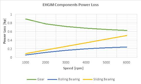
Figure 4 EHGM components power loss
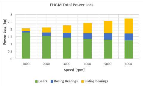
Figure 5 EHGM total power loss
Figure 6 is a comparison between frictional power losses of EHGM and the conventional piston over the speed range of the engine. Figure 7 is a comparison between efficiency of EHGM and the conventional piston over the speed range of the engine.
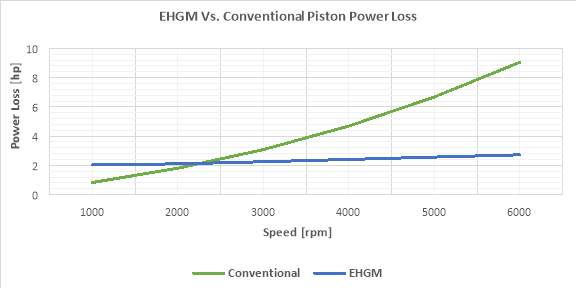
Figure 6 EHGM Vs. conventional piston power loss
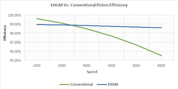
Figure 7 EHGM Vs. conventional-piston efficiency
7. Conclusions
This work was focused on the feasibility of EHGM as an alternative for conventional crank-slider mechanism in internal combustion engine applications. Since literature showed that HGM engine considers gears as the critical component in the design, it was given higher attention in this investigation. So, the gear set was designed using AGMA standard procedure and it was shown that it can withstand the engine load and satisfy all the engine specifications and requirements without exceeding the allowable stresses and allowable power rating.
Friction model for the interacting components in EHGM engine was developed. The model for gear friction losses was selected to be applicable to internal gear meshes with all calculated parameters satisfying the internal gear set specifications and geometries. The lubricant viscosity grade selected was based on the recommendations and guidelines provided by AGMA for gear meshes. The SKF friction torque model was selected to estimate the frictional power losses of the carrier rolling bearing. It was assumed that the same lubrication is provided for gears and bearings inside the crank case. Sliding bearings friction model was utilized from tribology and gear design handbooks for both the journal type and the planer-sliding type.
The validity of this model was assessed against the conventional crank-slider mechanism engine through selecting the same engine specifications for both, building the EHGM version, then estimating the frictional power losses and efficiencies for both over the engine speed range. The theoretical analysis done in this work shows promising results for the engine performance data in terms of minimized frictional power losses hence higher engine efficiency. So, the main concern about EHGM engine complexity, variety of components, and many frictional interfaces was proven to result in minimum losses as compared with the benefits of eliminating the conventional engine piston side thrusting.
The suggested future work is to investigate engines with higher power generation, check the feasibility of using spur/helical gears to transmit higher powers, decide on what lubricant should be selected for minimized friction losses and satisfy gear meshing requirements, investigate the effect of the lubrication method and crank case design on the load-independent power losses for gears and rolling bearings, and finally validating all these results through some experimental testing of a prototype for EHGM.
Cite This Work
To export a reference to this article please select a referencing stye below:
Related Services
View all


Related Content
All TagsContent relating to: "Mechanics"
Mechanics is the area that focuses on motion, and how different forces can produce motion. When an object has forced applied to it, the original position of the object will change.
Related Articles

DMCA / Removal Request
If you are the original writer of this dissertation and no longer wish to have your work published on the UKDiss.com website then please: